Saturday, October 29, 2011

CAD and The Devil


Shock Mounting Bracket Water Jet Cut from .188 Steel
Posted by PicasaI know, “a picture is worth a thousand words, and “tell the whole story”. But how useless are these really without some description in the form of text? I find I'm getting in to a bad habit of posting pictures with the intention of adding text later then conveniently forgetting to do so. I posted these pictures after I revised the swing arm design to make it more functional and easier to build. I still had to modify the 2 plates that were added as I decided that sliding them on to the tubes was a bad way to fabricate everything and that there was no need. Instead I made them so that they just weld on and can be placed after the rest of the swing arm tubes are already welded in place.  I cut a couple of pieces out on the waterjet and once I stop procrastinating and build a jig will tack everything together. Pictures to follow.

Sunday, October 23, 2011

Front Swingarm Update

I had to modify the front swing arm brace to make it something that I could easily make. In fact the modified part is simpler and was easier to make than my original design. By making the brace tube a single piece with a 192degree bend I was able to make more quickly and more accurately than the previous 3 piece welded design. I call this piece a brace but actually it’s main function is as the mount or actuator for the front shock. The swingarm main tubes are easily beefy enough for the job especially since there will be no braking forces (no front brake) and the lateral forces will be small compared to a street bike that is designed to go around corners.  Any lateral forces induced by turning or lean angle will be due to coarse correction or cross wind compensation and should be much smaller than what the forks of a street or track bike have to deal with.
Top Loop Against the Drawing

Loop In the Lathe Notching Jig for First Cut

Squaring up the top loop in the lathe Jig


The Bosch DWM 40L. Extremely useful for this kind of work. Far more accurate and versatile than a combination protractor square.


Rod End


Turned Inserts for the 5/8” Heim joints from 8620 steel. These fit into the 1-3/8” tubing and are welded into place. This will allow some adjustment of the front swingarm and make it easier to get the swingarm square with the frame and the rear swing arm pivot. These are from summit Racing and are similar to the Aurora HXMA Series Rod End Bearings though these have a radial Load Capacity of 21000Lbs.

Saturday, October 15, 2011

Frame Fab Begins!


Fine tooth (10tpi) hole saws make a huge difference when mitering thin wall tubing.  It was the difference between a smooth accurate cut and the saw grabbing and coarsely cutting  through the material occasionally breaking a tooth along the way.


The Under utilized JD2 Model 32 bender on my home made stand


I Bought this over a year ago for another project that is now on hold. these benders are relatively inexpensive and do a great job of easily bending even large diameter tubing. I'm doing 1.375x095 at the moment and was surprised at how easy it was to bend compared to the Diacro bender I had been using. In all fairness the Diacro was never meant to bend tubing larger than 1 inch or so. However with the JD I didn't even have to use a cheater pipe on the relatively short handle as it gives you that much leverage. And with the added leverage ratio also comes more precise control over the bend.
First miters cuts of the day 
.


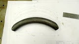
Here is the first bend of 1.375"x.065 wall. it's a 6.5" Center line radius with a 1.375" miter on each end. this is the center brace for the front swing arm which is the first frame piece I decided to make. That decision was based mostly on the fact that the other components are still in the design phase and subject to change where as the swing arm is done the drawings ready to go. Below is an image of the weldment model of the front swing arm so you can see where the parts I'm making here fit together.
Front Swing Arm Model In Solidworks


I am a complete green horn when it comes to working with tubing (even worse at laying out blog posts I might add). That said one of the fun challenges for me is figuring out how I’m going to accurately miter the tubing so that it fits together the way I have designed it. The videos on Youtube from guys trying to sell you a tube notcher show miters that are all dead easy to make. Most of the commercial notchers aren’t capable of making a very shallow miter cuts on a tube that already has a bend in it. They can’t be adjusted for cuts shallower than about 35 degrees, and only the very expensive ones can hold bent or non straight tubing. Hole saws also need a very ridged set up to cut well so again all but the expensive tube notchers out there aren’t very good in that department either. Motorcycle frames need to be much more accurate than roll cages or furniture, so starting with really precise clean cuts makes a huge difference. I've seen tutorial vidios on equipement manufacturrers web sites that show miters with large gaps between the tubes where the guys calmly states that he will just fill the hole when he welds the pieces together. Huge FAIL in my book. When it comes to a ridged set up a Bridgeport makes and excellent hole saw and that is what I used for the 2 cuts on the 1.375 cross brace. The 1 inch top loop brace is really for mounting and actuating the front Shock more than it is for actually stiffening the front swing arm. Where it meets the 1.375” main tubes is a shallow 15deg angle that produces a fairly long cut. I couldn’t think of an easy way to do this on the Bridgeport but had seen a notching system for using a lathe that seemed to offer an excellent solution (again a nice heave ridged machine tool). In the VMC I drilled and tapped a .75” piece of 7075 Aluminum with an array of ½-13 holes with some reamed 1.4” holes forfor pins for locating the work piece. There is a counterbored piece that bolts to the back of the plate that allows the whole fixture to be clamped into one of the Aloris tool holders so that it can be placed on and off the Aloris tool post easily. Moving the lathe compound slide is a very easy way to get very accurate angled cuts and also makes it very easy to adjust precisely where the saw starts to cut through the tube. Here you see the shallow 15degree cut that was actually very easy using this set up.


A Nice Fit


Posted by PicasaSome of the front swing arm parts ready for welding

Hub Spindle (steering Axis)


As much as I hate quoting the vapid philosophy of pop songs, they do sometimes sum up a thought or two nicely for you when you are too lazy to think of anything pithy yourself. Two such came to mind as I was preparing to write this. An abbreviated version John Lennon (or Allen Saunders) starts us off  “Life is what happens when you‘re making plans”. And the corollary question: How do you make god laugh? The point of all this is that I have been working elsewhere for another company at their shop in Brooklyn, and don’t get to my shop at all these days. I finally managed to get a couple of days to work on the bike and the following is what I have to show for it. This is the king pin or pivot for the hub center front end. It is the 1st op turned from 8620 steel. There will be a 1 inch hole bored through the center and 2 flats machined on the ball to provide faces for the axle spacers to locate on. This will hold the wheel in the center of the axel. As you can see it fits into a top and bottom tapered roller bearing which get loaded together via bolts that run through the hub and pull together the 2 “caps” that hold the outer races. As it turns out this is very similar to the front end that DiFazio filed a patent for in 1968. A copy of which is on line here:


The King Pin in place inside the Hub

 
And again from another angle so you can see how the "Caps" fit onto the hub and hold the steering bearings. 
Posted by Picasa