Saturday, November 26, 2011

Making God Laugh

“If you want to make God laugh, tell him about your plans.”
-Woody Allen

The EX250 Rim as it arrived
from The Ebay Ether. 
I started this weekend with my usual drastic underestimation of how long it will take to get parts finished. I decided to get the Front End finished up before I spent too much time on the frame lest I wind up with a bunch of unfinished parts all over the place. So this was an exercise in housekeeping as much as it was a push at self discipline. I suffer from a very short attention span and a low threshold of boredom so the way I attack projects is to break them up and focus on one part for however long it takes to lose interest. This may sound cynical but it works for me. After I make a certain amount of progress on a part or task I start another to keep things fresh. After a while I move on to a third part and so on. Eventually, after I have some distance, I go back and work on the original part. This also allows time to evaluate what has been done to either tweak the part design or the strategy for making it. The hardest part aside from keeping all the details in mind or not spending too much time trying to figure out where I left off when I do pick up a part again is making sure to actually finish pieces. Here (this post) is an example.
Apple Core
Precision Sawzalling

Looking back to my post from Feb 3 of 2010 I explain why I chose to use the front wheel I did. The Yamaha R6 Front rim seems to be a popular choice for people building hub center front ends. It has the requisite spacious hub and is set up for twin discs and modern tires so it’s an excellent choice. For me though I wanted a smaller and narrower rim so I went with the EX250 rim. The first rim I got wasn’t in great shape so I decided to get another one and use it as a backup. I got another on EBay that was in much better condition. I decided that getting the front end done this weekend was a priority  and wanted to machine this new rim and get the hub assembly fitted before moving on to frame bits. I assumed it would take me about 4 hours to cut the hub out of the new rim, mount it to the mill and machine it to fit the hub inserts. 2days later I had it finished. Did I mention I under estimate the time I need to do almost anything? My first mistake was in deciding to strip the cracked and peeling red paint off the rim before I started machining. The chemical stripper I have was very effective in turning the outer layer of paint into red goo while leaving the layers underneath unmoved. I have done a lot of auto body and paint work and chemically stripping paint is always a gamble. Cheap paints seem to be the hardest to get rid of because they turn into goo that is just a mess and time consuming to remove. I think someone here went over the OEM finish with Krylon because what I had in front of me was the kind of mess I have gotten time and time again when I try to chemically strip Krylon. Either way, after wasting 2 hours on that dead end I cleaned it up as best I could and decided to just blast the rest off. After blasting (another hour or so of my life not making progress) I had a clean rim ready for machining.
Ready to machine
Clean Aluminum rim after
Bead Blasting
 The hub inserts are 5.375 inches where they insert into the hub. After mounting the rim to the bed of the mill and very carefully locating (and Triple checking) the center with my Renishaw MP11 Probe, I found out that my very expensive and here to fore unused boring head wont bore a hole that big.
Locating the center rotation
of the rim by probing
the machined brake disk
I don’t like making round holes on the mill when roundness matters. I don’t have access to a lather big enough to spin this rim so the boring head was going to be the next best thing. I bought my mill new and aside from the abuse that Chris subjects it to it has seen relatively little use so it is still very accurate.  That said CNC mills still don’t produce perfectly round circles but at this point I had to go with what I have. The results were excellent though and the hub inserts are a beautiful light press fit into the rim. After drilling out what were the brake disk carrier bolt holes, I pressed the two hub halves in and am very happy with the fit. Once the rim is painted I can do the final assembly and call these parts done.

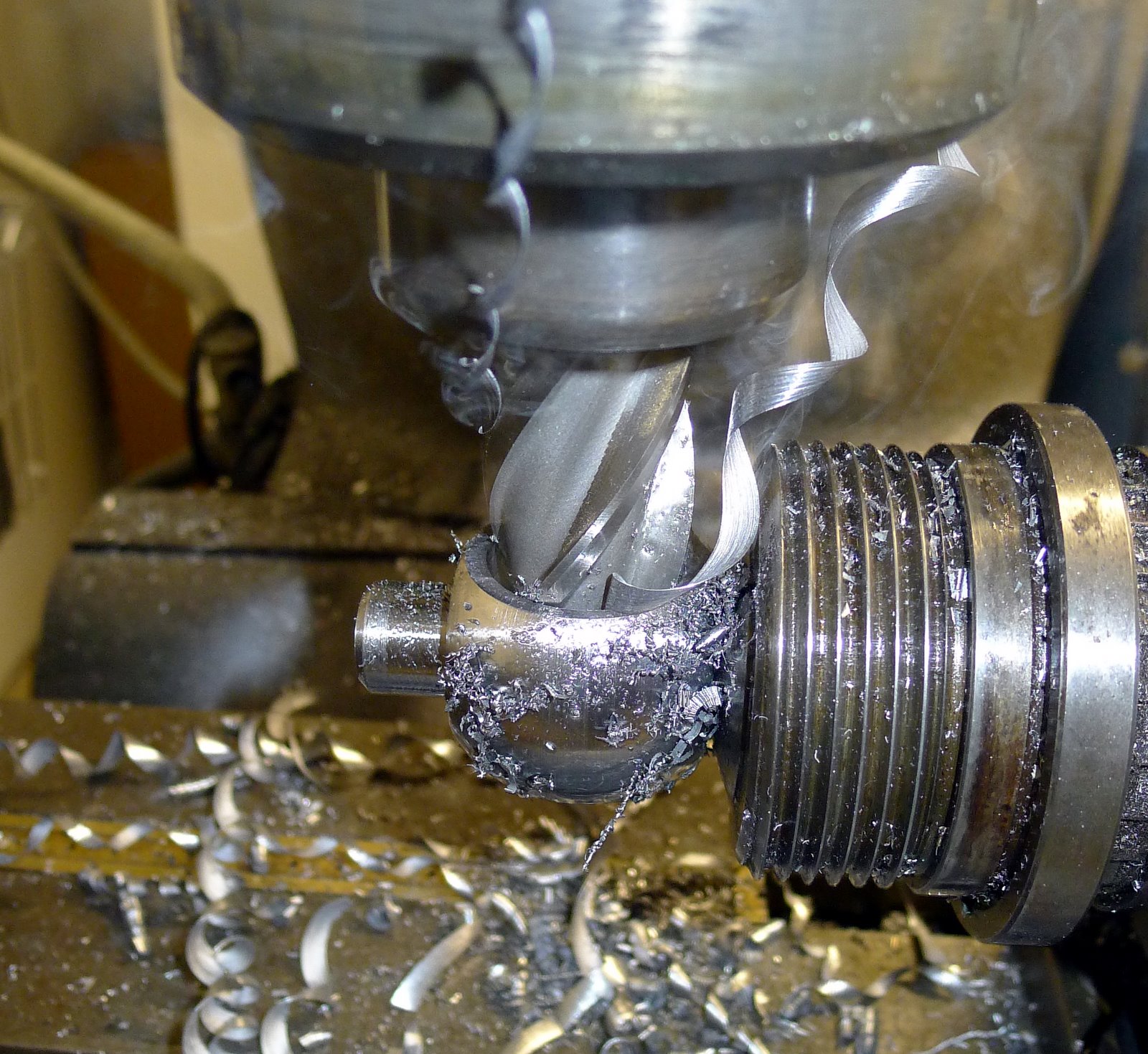
Rough machined to remove the
remnants
of the OEM Hub
Finished Surface


Posted by Picasa

Drilling out the disk carrier hols for the hub insert bolts
The rim with both hub inserts pressed into place. Rim Gets painted then final assembly

Tuesday, November 22, 2011

Little by Little


Posted by Picasa
Started Cutting frame pieces today.  This is the spine of the frame being notched in the jig I made for the lathe. The handy Smart Tool digital level allows me to make sure that the notches in each end of the tube are parallel. The tube is 1.375” X .095wall  4130.

Sunday, November 20, 2011

Da Frame, Da Frame


A couple of renderings of the frame model as it is at this point. After running some analysis ( I hack my way through FEA so I only use it as a guide and definitely not some definitive on frame design). I’ve made a number of revisions and I’m feeling confident that this is good and that there won’t need to be much revision from this point. However, only testing will tell. I plan to start fabricating what you see here shortly and have something of a rolling bike by the end of the year. That’s the goal anyway. I have to give props to Chris Cosentino and Tony Foale for input and insight on the process that lead to this frame design have given me the confidence to proceed from here. Although not pictured here, the front suspension was designed with Chris’s help using Tony’s suspension analysis software. I highly recommend both the software and Tony’s book on chassis design for anyone building any bike or those that just want a better understanding of how and why a motorcycle frame works.  Even if you are building Choppers, this book will give you the understanding to actually build a chopper that *gasp* handles well.


Posted by Picasa

Sunday, November 6, 2011

Lolly Pop

Held in the indexer for milling and drilling


The flats milled with a half-inch pilot hole drilled in the center

An excellent 1 inch hole


Kingpin sitting in one of the tapered bearing hub caps


Axel partially pressed into kingpin
This is the kingpin center of the hub center steering assembly. This is the pin on which the hub pivots. On a conventional motorcycle you have the steering stem which is the axis of rotation of the front steering assembly and the forks. On this bike, this is the center of the steering assembly likewise the rake and trail figures are determined by the angle at which this is positioned by front axle or more specifically through a measurement taken perpendicular from the ground. This was a piece I turned out of 4130 steel in the CNC lathe, as you can see in a previous post. Here I finish it by locating and boring the one-inch hole through the center on the Bridgeport.  I bought a new one-inch high speed steel end mill on eBay and after milling the flats on either side and drilling a pilot hole all I had to do was plunge the end mill through and center and I got a perfect one-inch hole. The fit is as good as if it had been reamed. The axle is a piece of 4130 tube with a.1875 wall and it is a nice light press fit into the kingpin as you can see in the last picture. The kingpin will also get welded to the axle and the angle of the kingpin will be determined by how the axle is clamped into the front swing arm. This is a very easy way to adjust the rake and likewise the trail figures to optimize the stability and handling once I am actually able to ride the bike and do some testing.
Axel partially pressed into kingpin 2


Posted by Picasa