Thursday, May 19, 2011

More on the Hub Center Inserts

Boring chuck jaws to hold the 8" aluminum rounds


A chunck of 6061 T6 ready to go. aircraft quality don-cha know.


 First op done on one of the two pieces. The two halves or pieces are not identical. Since the Kawasaki rim I'm using is not symmetrical about the center these inserts had to be slightly different.
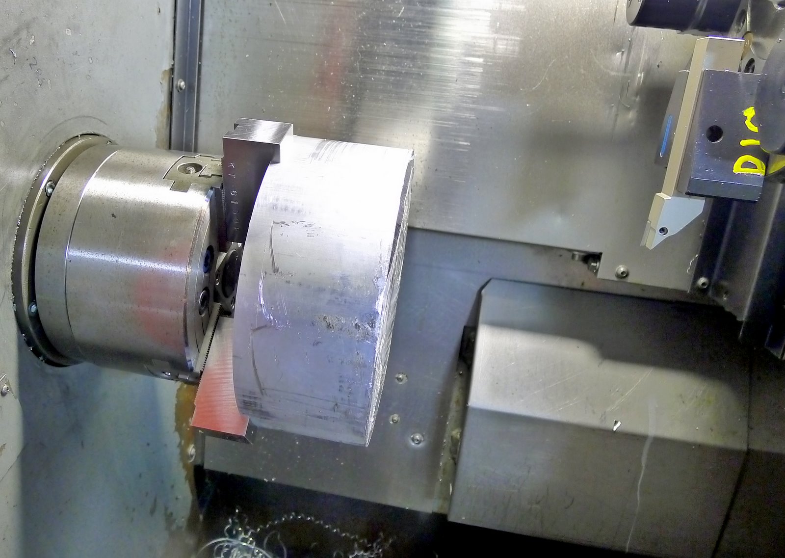
 6061 Aluminum is stringy stuff. you have to really push the cutting tool hard to get it to chip properly. the problem I had was that this is a relatively small lathe and a workpiece that diameter has a lot of leverage on the spindle and spindle motor. I was nearly maxing out the horsepower of my machine at the outer diameters. I suppose I could have taken less deep of a cut.
 One piec, first op done. Next op is done in the mill.
Drilled and Tapped (6mm X 1.0mm in 12 places) The other pieces just gets drilled and counter-bored. After that the pieces are contoured to shape.

Machining The right hub insert.
 The finished Pieces
The Finished pieces with the hub assembly and bearing.

Bearing Installed.
Hub Inserted

Complete Assembly. It's actually a lot lighter than it looks.


Posted by Picasa

The Beginning of the New End


The new rear end or final drive gear. I know this needs and explanation. I also know I have been pretty poor at not only making entries in this blog, but when I do, I tend to skip a lot of detail. I realize that I need to write more and that this is as much a diary for me as this will hopefully explain to someone not already familiar with what I'm doing just what all this means. I have been telling myself for the last few weeks, as I focused on paying work, that I would need to make 2 promises here. The first is that I would go back and structure this better and fill in the detail that will provide a proper narrative after getting my butt in gear and writing a true introduction with the goals and motivations that led me here. The second promise is that when I do get the time to make a little progress on the project that I will write a detailed entry here and try to really keep track of the progress (for lack of a better term).

First A bit of catching up. I finished machining what I call the left and right hub inserts for the Hub center front end. These are the parts that will attach to the rim hold the outer race of the baring and allow the wheel to rotate around the center hub. The next post will be about that process.
In the process of working on the hub I began thinking about the transmission and the final drive. I know that the gear rations with the current final drive weren’t right to give me anywhere near the speed I was hoping for. When doing the gearing calculations I missed one critical factor. I know that BMW transmissions are three shaft transmission with the first shaft being the input shaft. I also know that the only gear on this shaft was the one that made up, what is essentially the primary ratio. What I didn’t realize was how big the primary ratio was. Initially I thought it was 1:1 but after reading a bit I found a reference that referred to it as being 1:1.3.  Keeping this in mind I tried to verify the ratio of 6th gear by engaging 6th and counting the number of revolutions of the output shaft relative the a few turns of the input shaft. The numbers I was getting weren’t making sense. Initially I thought that I had bought the wrong transmission. I had specifically chosen this R1150Rt transmission because it supposedly had the tallest overdriven 6th gear of all the BMW transmissions and it was taller than any other similar transmission made by any other motorcycle manufacturer (Moto Guzzi, Honda, ect). But as I turned the input shaft the ratio wasn’t measuring out to be what I though 6th gear to be. Or at least what I had read that it was. I decided that opening the transmission cases and counting the gear teeth myself was the only way to be sure what the gear ratios I had actually were. So as per the excellent BMW service manual published by Clymer I heated the cases to 210F and opened the transmission up. That’s when I found that I did indeed have the right trans and that 6th gear was the tall over drive I was expecting. Now for the bad news. In my exploratory expedition into the transmission I found that the primary ratio was almost 1:1.8! After plugging this into my gearing speed excel sheet I found myself looking at a top speed in 6th gear with the engine at max RPM of only around 103mph. This was a huge disappointment, a huge setback and now I had to figure out a way of fixing this problem. I thought of having a new set of final drive gears made. Extremely expensive and would require a whole new final drive housing as well. I thought about replacing the primary gears in the transmission. This was simpler as they were straight gears and wouldn't have cost nearly as much to have made but still not too appealing. Next I thought of inserting a right angle drive directly after the transmission and bolting a sprocket to it to effectively create a chain final drive. This would allow me to easily play with the final drive ratios and ultimately I could easily increase the gearing as I find better power from the engine or improve the aerodynamics. The big stumbling block here though is, how do I mount the angle drive? There is no place on the transmission that is strong enough except the swing arm mounts and if I used those I would have to fabricate a whole rear sub frame to mount the rear shock and the new swing arm and that proved to be a very complicated task. In the end, with a little brain storming from Chris, what I remembered was that a number of Japanese motorcycle makers make bikes that are shaft driven but also have engines whose crankshafts run transverse to the direction of travel and so have to have what’s called a middle drive or middle bevel gear. I could easily think of a number of different models that had this arrangement and so I looked on eBay to see if I could find these parts used. Sure enough they are all over the place and quite cheep. After buying a number of sets, I settled on ones made by Kawasaki for their GZ1400 (Concourse) sport tourer. 
For one thing a bike that big and powerful will have gears that will easily meet my needs. Secondly, Kawasaki have been making a variant of that bike for 20 years so those parts are going to be easy to find, proven, and cheap. I got a set, disassembled the entire drive measured and made 3D solid computer models. This allowed me to fairly easily design a completely new final drive that will still use the BMW transmission, swing arm and rear wheel and give me the ration I need to reach the speeds I think I can reach with this project. I ran into a little problem with the rear axle or what I call the rear spindle. First it has to mate properly to the BMW rear wheel. So that mount is a given. Next, because where the spindle meets the wheel is relatively large, BMW uses a Big bearing (85mm ID 125mm OD) for support. The Kawasaki Drive gear that I planned to use was made to press onto a splined shaft that had a major diameter of only 27mm. I initially designed a new spindle that had this 85mm bearing surface and then reduce to have a 27mm spline behind it. The problem here was there was no way to cut the spline. After thoughts of shaping it by using a cutter locked onto the oriented spindle of the CNC mill and running it back and forth till the spline was effectively cut, Chris though that a better way would be to pin the gear to the spindle with dowel pins and just capture it with a thread and nut. A thread would be easy to cut on the spindle and so that’s the direction I went. I have never done any hard turning or hard machining and know that gears are usually case hardened for wear resistance. I was a bit worried about machining this gear so that it would work in this new design. I even went so far as to pay a visit to a local gear cutting house to ask the owner for advice. As it turns out it’s wasn’t very difficult at all. Even though according to Steve at Apex Gear the gears I had in my hand were case hardened to ~62Rc, it was most likely only case hardened to .02” deep and most good carbide tools should go right through the case. I ordered a letter C solid carbide drill and .2395 carbide reamer and took the above pictures as I drilled the holes in the Bridgeport using the DRO to locate the holes on a circle on a flat on the rear of the gear. Those are .25” dowels and now that they are pressed in I can finish making the spindle and the other components of the new rear drive. I’ll try to post some pictures of the 3D models so you can see what I’m going for.