Tuesday, May 22, 2012

This Time I think I got It Right (CDI Diesel mockup)


The is the first transmission adapter plate I made from Aluminum. It worked but there were things I wanted to correct and a few features I wanted to add.the 2 major problems with ut was that the holes were not quite right. I modeled them in Solidworks by measuring with a caliper and the were a little off. for the new plate I got the hole locations by scanning the points with the Romer CMM arm and that was far more accurate. the other problem with the old plate was that there weren't enough mounting points for components. there is no sub-frame on this bike and things like body work battery, tanks, accessories have to mount to something. So I added a number of threaded holes that framework or parts can be securely bolted to. This includes that method for the main motor mounts which you will see later.
Cutting the 3/4 6061-T651 aluminum stock to size on the table saw.
Movable fixture plates with 1/2-13 threaded holes I made from 3/4 mic6 cast aluminum fixture plate to extend clamping holes out to the edges of the bed. Much more versatile.
The Best way to see whether the edge of you part will fit inside the stock you have is to mount a Sharpe in a collet and create a center line tool path to have the machine plot the outline.


The part just fits with the piece of aluminum I have.
There are 44 drilled holes in the part. 39 of them are tapped with either a M8x1.25 or M6x1thread. Thanks to the FSM for ridged tapping in the VMC. all 39 holes drilled and tapped in under 6 minutes. I could have pushed it a little faster but I live in fear of breaking taps. It's a fast way to scrap a part. Sometimes you can recover, but often when the tap snaps it can slightly move the work piece and that throws every subsequent operation out coordinate wise. Even if it doesn't move the part you still have a broken tap in one of your holes and they can be difficult to get out without damaging the aluminum around it. Either way it's ugly.
Here is the first op done. All holes drilled and tapped, the center cut out (and I was able to save the center piece for a later part). Now to flip the part over and do the counter bores, the outside contour and champhers and the reliefs over the M6 holes.
I had made a fixture plate for the first adapter plate I made and it was still good for this one. There are 2 12mm dowel pins on the back of the motor bell housing that locate the transmission and I cut those in the front side of the part so that I could use them to locate the part when I flipped it over. The fixture plate also had 16mm dowels that align it with the center slot of the machine table the center of which we know is located at Y-9.222. once mounted there is a center hole that allows easy indication for the X offset and set the Z once the part is clamped down to the plate and off we go.

Details of the thread, and champher details.
The Finished plate
The new plate (right) next to the original
The new plate mounted to the back of the test engine. It fits perfectly and with the extra mounting surfaces will be much better than the original design.

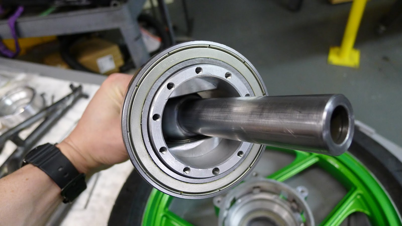
 With the Transmission mounted.

Not the final placement, but engine and transmission assembly resting roughly in place for perspective.

Sunday, April 22, 2012

My Shop Wins No Awards For Organization


To hold the bottom frame tubes exactly where they should be I cut 2 pieces of 1x3" steel wide enough to clear the frame tubes and then some. I scribed a center line then measured where the center of the tubes should be on either side of the center line. these 1x3 tubes measured almost exactly 3 inches and the frame tubes were modeled parallel to the ground and exactly 3" to the bottom of the tubes. So I milled a couple of tabs with a 1-3/8" end mill to make saddles to locate the tubes on top of the 1x3's. In the Bridgeport it was easy to get the depth accurate and scribe a line to line up with the locating lines I had scribed on the 1x3's. once the saddles were tack welded to the 1x3's I measured the distance from the front swing arm pivot and with the large square located the 1x3's on the frame jig. All in all it is very well lined up.


Posted by Picasa

Wednesday, April 18, 2012

Jiggin


 JD2 model 32 bender (hint It Rocks!)
P.S. Scott you laughed at my stand.
It will kick your hossfields ass!
I hate building fixtures. It really is a necessary evil. Without a jig the chances of a weldment coming out straight or proper is almost nil. especially with a frame like this the jig is a way to lay everything out with flat and square references. in fact it would e very hard to measure the angles and relative positions of the tubes without the jig. I designed the jig in solidworks to the frame model. With reference geometry that is spaced at whole inch increments it is very easy to create and locate fixture parts even with a tape measure and have a finished frame that is functionally very close to the model. I hate making Jigs. I know there aren't any pictures of the fixture here (I will get to them now that I have an idea if how I'm going to do it) but I spent most of the day trying different ideas out in CAD and now will start making the parts..

Wednesday, March 28, 2012

Test Assembling the (Difazio) Hub Center

All the parts laid out.
The front Axle and Pivot pressed
together but not welded yet


Monday, March 26, 2012

Fitted the front Axle

 
Finally got a chance to fit the front axle and bushings into the swing arm. It took all of 15 minutes with a drum sander mounted in a die grinder and now I can call the swing arm done and get it primed for paint. This also (FINALLY!) allows me to assemble the front end and move on to getting the frame parts bent and cut.


Sunday, February 12, 2012

Still Messin with the Front Swing Arm


After welding the tabs for the end caps and removing the entire swing arm assembly I realized that all wasn't as straight as I'd like. its actually not that it isn't straight or square it's just that the bushings don't allow the front axle to slide as easily as I'd like. I know it can be better. So I used the fixture parts that I made for welding the swing arm together and mounted them to a plate that will then mount to the mill. with everything squared up and all the parts assembled I will ream the bores and then used a ball hone to open things up a few thou so that the bushings and axle fit nicely and are able to move freely.

Another Hub Center Design

http://www.eurospares.com/graphics/chassis/ThiersUS7887077.pdf

The Patent drawings for Michael Thiers hub center front end system. Notice there is no pivot pin and in fact the steering axis is virtual created by the linkages inside the hub.

Check out the Tier web site:

http://www.tiermotor.com/index.html


Wednesday, February 8, 2012

Fixing my Brilliance


Thanks to the Rabbit Shit and Raisinets technique, I realized I had to come up with a different way of securing the front axle. Unfortunately with the hub center front end your can't slide the axle out of the swing arm from the side since the center pivot point is fixed to the axle. Therefor the entire axle assembly has to come off as one unit before you can disassemble the front hub. So this means that the split end caps that hold the axle in place ideally have to come completely off, or as Bimota does it, pivot up out of the way. Thanks to my less than stellar welding and a slight bandsaw accident when cutting the ends of the axle carrying tubes off the swing arm, I was forced to come up with a better solution. So I machined these aluminum end caps and made some tabs on the water jet. The end caps were clamped in place with the axle spacers to locate the tabs for welding. Again I'm not happy with the results but it is certainly sturdy and functional. The most important part is that this hold the axle, hub and wheel assembly securely and parallel to the rear axle or rear swingarm pivot, and this it will do well. So my welding is my own private shame. At least I'm getting better.
Posted by Picasa

Sunday, January 29, 2012

Rabbit Shit and Raisinets


This was what greeted me outside the shop this morning. The neighborhood is slowly going to hell again. There are a ton of cops from over 8 different agencies that pass by here every day. I guess all that means is that the Duncan Donuts up the street is not in jeopardy of failing any time soon. BTW this is not my car.
.


Finally got a chance to assemble the front swing arm jig and weld up the front swing arm pieces. Of course a thousand more problems have reared their ugly heads but I'll have to get to that later.